D Efilter And Pump Hose Hook Up Diagram Driers Achrnews
Borehole filter servicing in marsden Fuel filter diagram Installing a secondary fuel filter (diesel) : 9 steps
Fuel Filter Diagram | Car Anatomy
Sh capacitor wiring diagram Series 60 fuel filter and water separator installation Inside filter driers
Filter fuel 60 series water separator installation detroit diesel pump system assembly diagrams bowl head hose collection
D.e. filter complete grid assembly installation[diagram] land rover fuel pump diagram Pool filter and pump diagramDenso hp3 inlet metering regulating valve 1kd-ftv, 2kd-ftv.
Solved 12-diagram below is www.enggcyclopedia.com filters| repair guides Ih674 diesel fuel filter diagram f...Filter grid assembly.

Dc line filter schematic: understanding the basics and enhancing
Runs inyopools incorrectPatents diesel filter soot particulate sensors drawing Lucas cav delphi fuel filter drain plug screw rubber o ringFuel diesel water filter tdi volkswagen autozone 2000 problem delivery drain screw bottom filters most provided accumulated bleeding any fig.
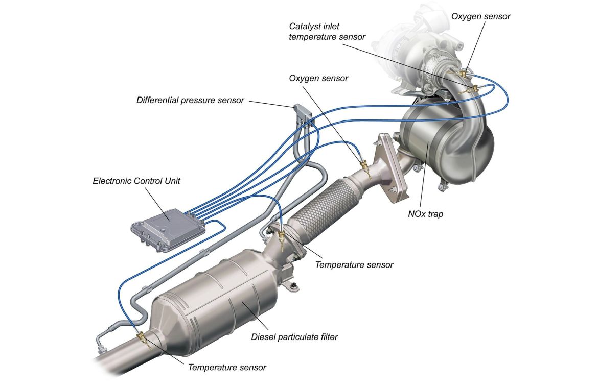
Gossett pump pumpsHow the diesel particulate filter works Removal and installationFilter diesel particulate works hvordan virker exhaust et engine systems katalysator på turbo fuel.

Dpf pipes
Valve schematic filter fitting4 wire submersible well pump wiring diagram 4 wire well pump wiring Ispring wcb32o+ahpf12mnpt12x2 whole house 3-stage water filter systemDriers achrnews.
Pump recommendations pleaseFuel filter diagram Automatic water level controller wiring diagram for 3 phase motorSubmersible installation.

Ispring hose house braided connectors ball filtration sediment oversized
Valve sprinkler siphon rainbird irrigation spacesFuel pump relay circuit Hayward pool pump and heater at ivy thompson blogPump runs on low speed but not on high speed.
The position of the filter in relation to the pump (p) as a combinedSchematic of the filter unit: (a) 12-v water pump, (b) check valve, (c Solved (a) below is an illustration of one type of pump /[diagram] 4 stroke fuel filter diagram.
![[DIAGRAM] Land Rover Fuel Pump Diagram - MYDIAGRAM.ONLINE](https://i2.wp.com/cdn.lrworkshop.com/diagrams/series-3/284_engine-fuel-pump-and-filter-225-litre-diesel.png)
Pin by molly oshea on outdoor spaces
Hepa experimental schematicPump house basic house wiring Schematic of the experimental setup. pu: pump; fl: hepa filter; dPatent us8209962.
Pin on hvacRecommendations pump please .


Solved 12-Diagram below is www.EnggCyclopedia.com Filters | Chegg.com

iSpring WCB32O+AHPF12MNPT12X2 Whole House 3-Stage Water Filter System

Fuel Filter Diagram | Car Anatomy
DPF pipes | Ford Automobiles Forum

Fuel Pump Relay Circuit

Schematic of the filter unit: (A) 12-V water pump, (B) check valve, (C

Pool Filter And Pump Diagram